How to Read Commercial HVAC Blueprints: Our Expert Guide
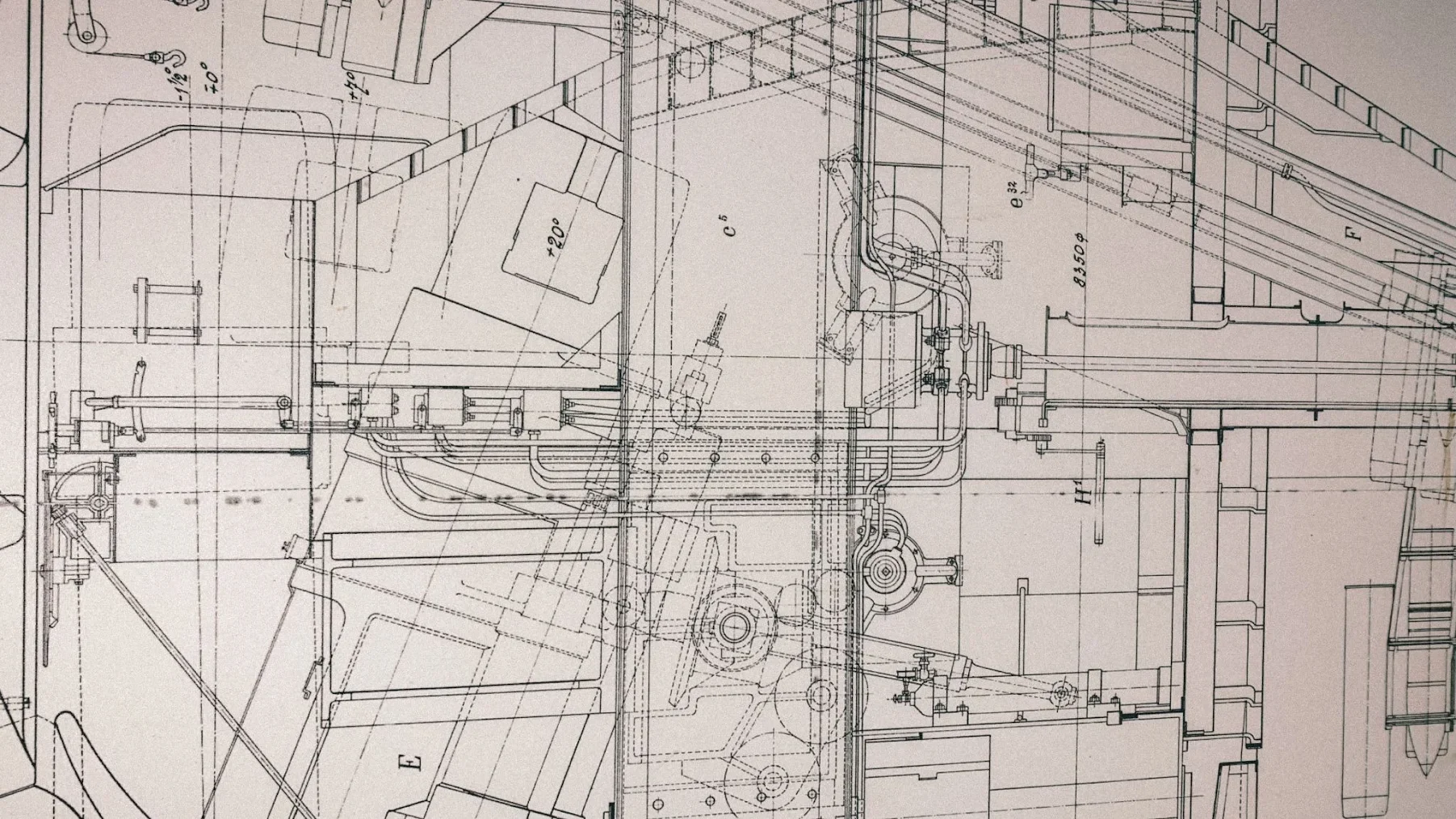
Commercial HVAC blueprints show how heating, cooling, ventilation, ductwork, piping, controls, and equipment are planned for a building.
If you know how to read them, you can better understand how your system is supposed to work, where key components are located, and what technicians may need to inspect, repair, or modify.
Take a look at our expert guide on how to read commercial HVAC blueprints.
What Are Commercial HVAC Blueprints?
Commercial HVAC blueprints are technical drawings that show how a building’s mechanical systems are designed and installed. They may include ductwork, diffusers, vents, rooftop units, boilers, chillers, exhaust fans, piping, dampers, controls, thermostats, sensors, and equipment schedules.
These drawings are usually part of a larger set of construction documents. A full plan set may also include architectural, electrical, plumbing, structural, fire protection, and control drawings.
The HVAC portion helps contractors understand where equipment belongs, how air or fluid should move through the building, and how different parts of the system connect.
What Should You Look at First?
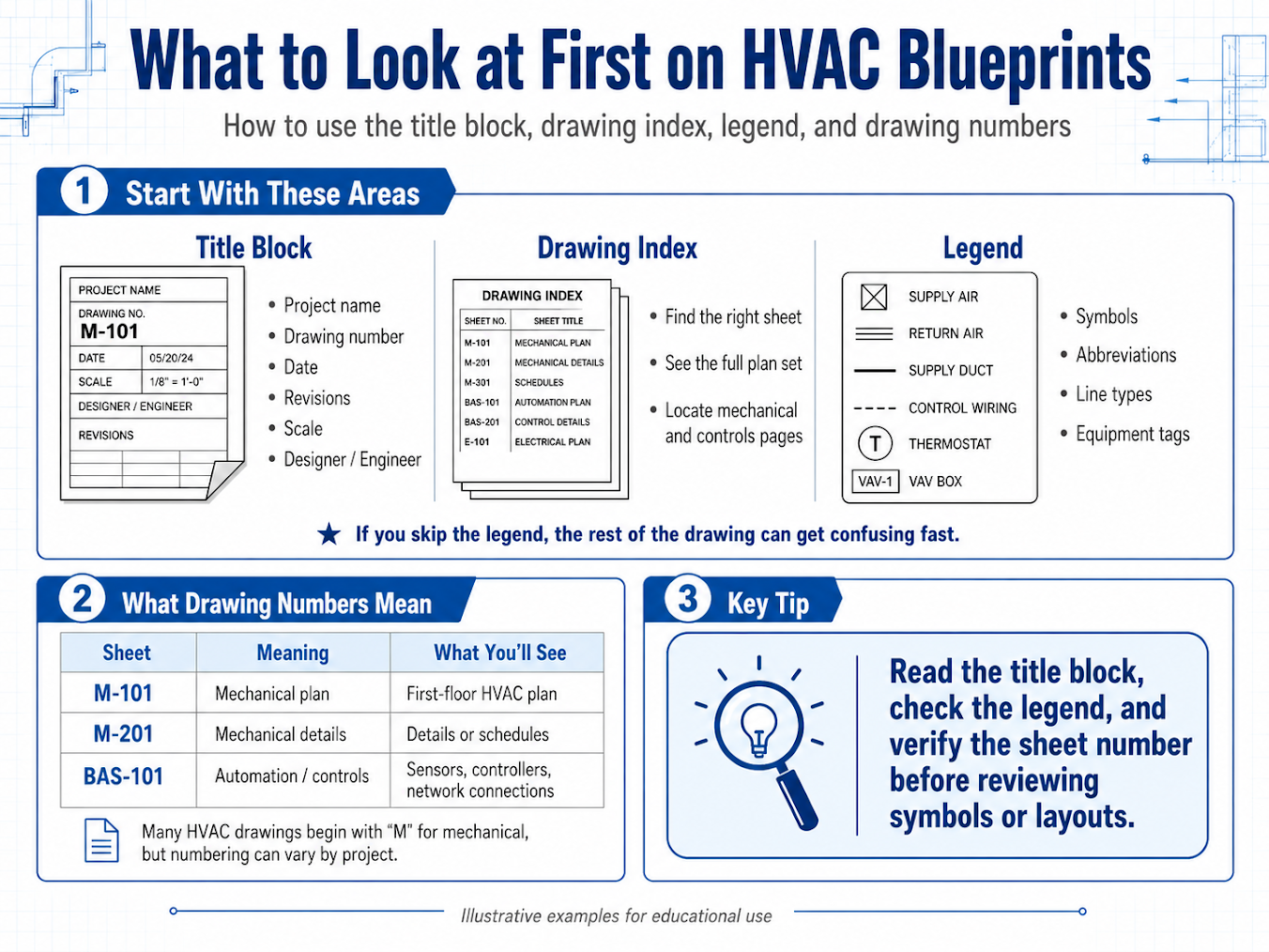
Start with the title block, drawing index, and legend. These sections tell you what you are looking at and how to read the symbols on the page as they relate to your commercial HVAC system as a whole.
The title block is usually found in the corner of the drawing. It includes the project name, drawing number, date, revision information, scale, and sometimes the designer or engineer. The drawing index helps you find the right sheet in a larger plan set.
The legend explains symbols, abbreviations, line types, and equipment tags. If you skip the legend, the rest of the drawing can be confusing quickly.
What Do Drawing Numbers Mean?
Drawing numbers help organize the plan set. HVAC drawings often start with “M” for mechanical. For example, M-101 may show a first-floor HVAC plan, and M-201 may show mechanical details or schedules.
Controls drawings may have a different numbering system, depending on the project. Some buildings also have separate BAS or automation sheets that show sensors, controllers, network connections, and control sequences.
How Do You Read HVAC Symbols?
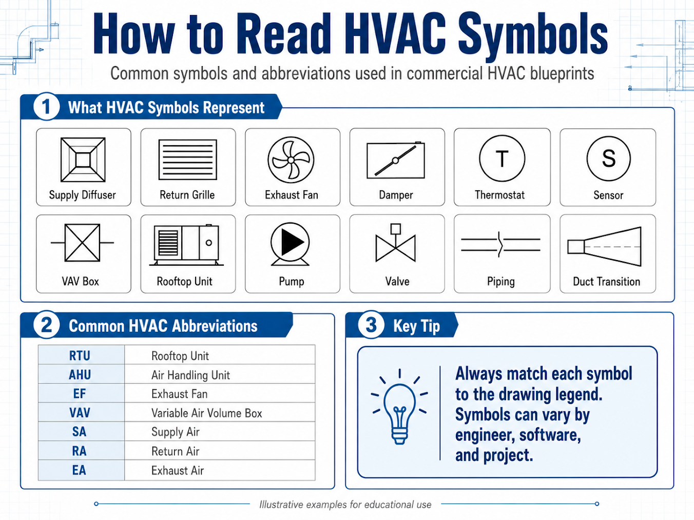
HVAC symbols represent equipment, devices, airflow paths, and system components. Common symbols may show supply diffusers, return grilles, exhaust fans, dampers, thermostats, sensors, VAV boxes, rooftop units, pumps, valves, piping, and duct transitions.
The key is to match each symbol to the legend. Do not assume every drawing uses the same exact symbols. Different engineers, contractors, and software programs may show symbols slightly differently.
Abbreviations are also common. You may see RTU for rooftop unit, AHU for air handling unit, EF for exhaust fan, VAV for variable air volume box, SA for supply air, RA for return air, and EA for exhaust air.
How Do You Read Ductwork Layouts?
Ductwork layouts show how air is distributed through the building. Supply ducts deliver conditioned air to rooms. Return ducts bring air back to the system. Exhaust ducts remove air from spaces that need ventilation or pressure control.
On the drawing, ductwork is often shown as lines or rectangular paths with size labels. A label such as 24x12 means the duct is 24 inches by 12 inches. Arrows may show airflow direction.
Look for how the ductwork connects to major equipment, branches into different spaces, and ends at diffusers or grilles. This helps you understand how each area is served.
How Do You Understand HVAC System Layouts?
To understand the system layout, follow the path from the main equipment to the spaces it serves. Start with the rooftop unit, air handler, boiler, chiller, or other central equipment. Then follow the ductwork, piping, or control connections outward.
This approach helps you see the system as a whole instead of a collection of separate parts. It also helps explain why one issue can affect several areas of the building.
For example, one rooftop unit may serve multiple offices, corridors, and conference rooms. If that unit fails, all connected spaces may be affected. If only one room has a problem, the issue may be closer to a diffuser, damper, sensor, or branch duct.
How Do You Compare Blueprints to the Actual Building?
You compare blueprints to the actual building by walking the site and checking whether the installed system matches the drawings. This is called field verification.
Buildings change over time. Equipment gets replaced. Walls move. Tenants change. Controls are upgraded. Ductwork may be modified. That means older drawings may not always match current conditions.
This is why documentation is so important. ACS Services is extremely focused on project records, and reports go out the next business day after work is completed. That gives your team a clear record of what was found, what was repaired, and what may need follow-up attention.
When Should You Call a Commercial HVAC Expert?
You should call a commercial HVAC expert when the drawings are unclear, your system is not performing correctly, or your facility needs repair, maintenance, renovation, or control upgrades. A technician can review the drawings, inspect the field conditions, and explain what is actually happening.
This is especially important for commercial facilities with critical environments, UPS rooms, data rooms, boiler plants, building automation, or complex rooftop equipment. In these spaces, a small misunderstanding can create bigger operational issues.
ACS Services provides commercial HVAC support with 24/7 service, strong documentation, and direct communication. When you call, you often speak with the owner, which helps you get answers faster when your building systems need attention.
Making Sense of Your Blueprints with ACS Services
Commercial HVAC blueprints can look complicated at first, but they become easier to understand when you know where to start. Review the title block, legend, equipment schedules, symbols, ductwork, system layouts, and controls drawings. Then compare the drawings against what is actually installed in the building.
A good blueprint helps your team understand the system. A good HVAC partner helps connect that drawing to real-world performance, maintenance needs, and repair decisions.
If you need help reviewing commercial HVAC drawings, troubleshooting system layouts, or planning work in your facility, contact ACS Services to talk through your next step.